
MEMS technology builds on the core fabrication infrastructure developed for silicon integrated circuits. Pressure sensors, one of the first high-volume MEMS applications, now monitor pressure in hundreds of millions of engine manifolds and tires; and MEMS accelerometers have been used for more than 15 years for airbag deployment, rollover detection, and automotive alarm systems.
MEMS accelerometers are used for motion sensing in consumer applications, such as video games and cell phones while MEMS micromirror optical actuators are used in overhead projectors, HDTVs, and digital theater presentations. In recent years, MEMS microphones have begun to proliferate the broad consumer market, including cell phones, Bluetooth headsets, personal computers, and digital cameras.
This article describes some of the key technologies deployed in MEMS accelerometer products and discusses how this technology can bring a new dimension to acoustic transducers.
MEMS Accelerometer Technology
The core element of a typical MEMS accelerometer is a moving beam structure composed of two sets of fingers: one set is fixed to a solid ground plane on a substrate; the other set is attached to a known mass mounted on springs that can move in response to an applied acceleration. This applied acceleration (Figure 1) changes the capacitance between the fixed and moving beam fingers.
 Figure 1. The structure of a MEMS accelerometer |
MEMS structures (Figure 2) are typically formed from single-crystal silicon, or from polysilicon deposited at very high temperatures on the surface of a single-crystal silicon wafer. Structures with very different mechanical characteristics can be created; spring stiffness, the mass of the sense element, and the damping of the structure can all be controlled and varied by design resulting in sensors that can measure fractions of one g or hundreds of g's with bandwidths as high as 20 kHz.
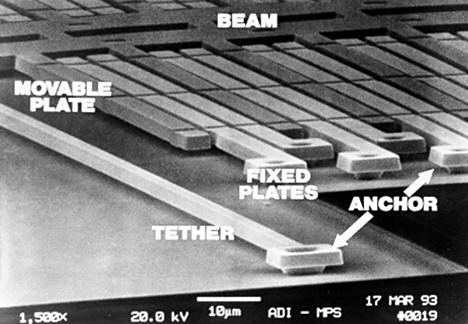 Figure 2. Micrograph of the ADXL50 MEMS accelerometer's structure |
The MEMS sensing element can be connected to the conditioning electronics on the same chip (Figure 3) or on a separate chip (Figure 4). For a single-chip solution, the capacitance of the sense element can be as low as 1–2 fF/g, equating to measurement resolution in the attofarad (aF) range. In a two-chip structure, the capacitance of the MEMS element must be high enough to overcome the parasitic capacitance effects of the bond wires between the MEMS and the conditioning ASIC.
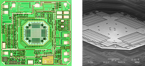 Figure 3. The ADXL202 ±2 g accelerometer (Click image for larger version) Figure 3. The ADXL202 ±2 g accelerometer (Click image for larger version) |
 Figure 4. Cross-section of a typical two-chip accelerometer |
Accelerometers as Vibration Measurement Sensors
The concept of using vibration sensing transducers as acoustic pickups in musical instruments is not new. Piezo- and electromagnetic transducers are the basis for many of today's acoustic pickup applications. Tiny MEMS accelerometers are so small and low in mass that they have no mechanical or mass loading effect on the instrument, making them attractive for these applications; but to date their use has been limited due to the narrow bandwidth of commercially available acceleration sensors.
Some recent breakthroughs in accelerometer technology have enabled the production of very small accelerometers with very wide bandwidth. A high-g (±70 g to ±500 g), single-axis accelerometer, such as Analog Devices' ADXL001 (Figure 5), has 22 kHz bandwidth and comes in a 5 × 5 × 2 mm package. This is ideal for monitoring vibration to determine the state of health of motors and other industrial equipment by detecting changes in their acoustic characteristics. This particular sensor is not sensitive enough for use as an acoustical vibration sensor for musical instruments. Also, it only senses along one axis of motion, while an ideal acoustic sensor will measure the response along all three axes. It does demonstrate, however, that full audio bandwidth acceleration transducers can be produced using MEMS technology.
 Figure 5. The frequency response curve of the ADXL001 |
Low-g accelerometers can measure acceleration down to milli g's, but are typically bandwidth-limited around 5 kHz. This limitation may be associated with the fact that few commercial applications require significant bandwidth (the primary applications involve the detection of human motion or gravity-driven acceleration), so there has been little motivation to develop sensors suited specifically for audio-band measurement.
A 3-axis accelerometer has three separate outputs that measure acceleration along the Cartesian X, Y, and Z axes. As an example, Analog Devices' ADXL330 3-axis, low-g accelerometer has a bandwidth up to 6 kHz on the X and Y axes, and around 1 kHz on the Z axis. While not ideal, this expanded bandwidth allows the part to gather useful information in the audio band. The output is analog, so it can be easily instrumented and used with standard audio recording equipment. Because its size is less than 4 × 4 × 1.45 mm (Figure 6), the sensor can fit into very small places and it does not cause mass loading or other changes in the response of the system being measured. Later we will explore how this low-g accelerometer can be applied as an acoustic pickup for a guitar.
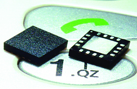 Figure 6. The ADXL330 MEMS accelerometer measures 4 mm × 4 mm × 1.45 mm |
Acoustic Feedback
Beginning with the introduction of omnidirectional condenser and dynamic microphones in the mid-1920s by Søren Larsen, the Danish scientist who first discovered the principles of audio feedback (known as the Larsen effect), acoustic feedback has been a demon few audio engineers are able to totally control, making it unavoidable in live sound. The Beatles experimented with this audio artifact, then decided to add it to their memorable introduction to "I Feel Fine" in 1964. Rock 'n Roll then set out to tame the beast by embracing it, making acoustic feedback a striking characteristic of rock music. Electric guitar players such as Pete Townshend and Jimi Hendrix deliberately induced feedback by holding their guitars close to the amplifier. As the fad waned, audio engineers continued their struggle with acoustic feedback's undesirable ear-shattering effects, particularly in live sound applications. In the perfect world of a well-appointed and acoustically treated recording studio, a high-end omnidirectional microphone will record instruments with an astonishing degree of realism and fidelity. Artists who know and cherish this sound have long sought the ability to reproduce it on stage. Although recording a live show with studio sound quality is every musician's dream, it has been virtually impossible. Even if sound reinforcement rigs sounded good, arenas had excellent acoustics, and sound engineers knew everything there was to know about mixing sound and had the best gear available, there would still remain one obstacle on the road to sonic nirvana: acoustic feedback.
Acoustic Pickups
Acoustic feedback is typically minimized by using directional microphones. This works to a certain extent, but requires constant management by sound engineers to adapt to the changing characteristics of a stage venue.
Musical instruments can be amplified using pickups. The technologies vary, but the basic idea is to sense the vibrations of the instrument's body directly, rather than the sound it produces in the air. The pickups generate almost no acoustic feedback, as they are not sensitive to airborne sound. However, finding a good-sounding location on an instrument body is notoriously difficult, the sonic characteristics of piezo pickups are far from perfect, and their high output impedance requires special instrument inputs or direct boxes. In addition, they can be large and can interfere with the natural acoustic behavior of the instrument.
This leads to the idea of a low-mass contact microphone. Suppose that we use a surface transducer that measures the acceleration of the instrument's body, preferably on more than one axis. This transducer would have good linearity and be so lightweight that it would not acoustically affect the instrument being measured. Suppose further that the transducer has similar output level, output impedance, and power requirements to a traditional microphone. In short, suppose that a musician could just plug this transducer into a microphone preamp or mixer input, just like any other microphone.
Contact Microphones
An attentive reader will notice the mention of acceleration in the preceding paragraph. Our ears respond to sound pressure, so microphones are designed to sense sound pressure. To simplify matters greatly, the sound pressure in the immediate vicinity of a vibrating body is proportional to acceleration. What if an accelerometer had enough bandwidth to be used as a contact microphone?
To explore this concept, we mounted a 3-axis accelerometer on an acoustic guitar to act as a pickup. The vibration of the instrument was measured and compared to the built-in piezo pickup and to a MEMS microphone mounted near the guitar. The guitar used was a Fender Stratacoustic acoustic with a built-in Fender pickup. An analog output MEMS accelerometer was mounted on a lightweight flex circuit and attached to the guitar body using beeswax at the bridge location, as shown in Figure 7. The X-axis of the accelerometer was oriented along the axis of the strings, the Y-axis was perpendicular to the strings, and the Z-axis was normal to the surface of the guitar. A MEMS microphone with a flat frequency response out to 15 kHz was mounted 3 in. from the strings for use as a reference.
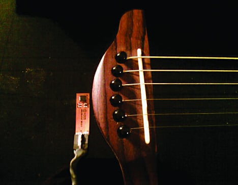 Figure 7. Accelerometer mounted on a Fender Stratacoustic Acoustic Guitar |
A short sound segment was recorded using the accelerometer, the built-in piezo pickup, and the MEMS microphone. The time domain waveforms for each transducer are shown in Figure 8. No postprocessing was done on any of the audio clips.
 Figure 8. Time domain waveforms using different transducers |
Figure 9 shows an FFT-based spectrum of the piezo pickup measured at one of the peaks in the time domain waveform. This spectrum shows a response with a strong bass component. Indeed, the actual audio file sounded excessively full, with a lot of bass response. This sounds pleasing (depending on your taste) as the cavity resonance creates a fuller bass sound than that heard when listening to the instrument directly.
 Figure 9. FFT spectrum of piezo pickup |
The MEMS microphone output is very flat and reproduces the sound of the instrument very well. It sounds very natural, well balanced, and true to life. The FFT-based spectrum measured at the same point in time as the piezo pickup is shown in Figure 10A. The frequency response of the MEMS microphone is shown in Figure 10B for reference.
 Figure 10. The FFT-based spectrum of a MEMS microphone (A) and its frequency response (B) (Click image for larger version) Figure 10. The FFT-based spectrum of a MEMS microphone (A) and its frequency response (B) (Click image for larger version) |
The output from the MEMS accelerometer is very interesting. The immediate weak points are that the noise floor was too high and audible at the beginning and end of the track, and that the bandwidth of the Z axis was clearly limited to lower frequencies. The sound reproduction from each axis was noticeably different.
The X and Y axes sounded bright and articulate and had clearly discernable differences in tonality. As expected the Z axis obviously sounded bass dominated. Figure 11 shows the X-axis spectrum (A), the Y-axis spectrum (B), and the Z-axis spectrum (C).
 Figure 11. MEMS accelerometer output showing the spectrum of the X-axis (A), Y-axis (B), and Z-axis (C) (Click image for larger version) Figure 11. MEMS accelerometer output showing the spectrum of the X-axis (A), Y-axis (B), and Z-axis (C) (Click image for larger version) |
The X, Y, and Z axes mixed together produced a fair representation of the instrument with some brightness. By adjusting the mix, a variation in tonal balance can be achieved with natural sound reproduction. The extended upper harmonics are still missing due to the bandwidth limitation of the current accelerometers, but the sound reproduction was still surprisingly true.
Conclusion
Low-g MEMS accelerometers do not suffer from traditional feedback problems, and demonstrate clear potential as high-quality acoustic pickups for musical instruments. A 3-axis accelerometer mounted on a Fender Stratacoustic acoustic guitar achieved promising sound reproduction. The three axes have different tonal characteristics related to the vibration modes of the instrument in the different directions of the body, however the three output channels can be mixed to generate realistic sound reproduction. In addition, these channels can be mixed in different ways to produce creative tonal effects.
While the performance of the accelerometer in this experiment is very promising, there are a few drawbacks. The noise floor of the sensor is audible, a problem that can be minimized using noise gating or other techniques, but the ideal sensor will have a noise floor comparable to conventional microphones. The high-frequency response of the sensor needs to be extended, ideally up to 20 kHz to capture the full tonal range of the instrument.
MEMS accelerometer technology has clear potential for acoustic pickup applications in musical instruments, especially in live performances where acoustic feedback could be a problem. A very small, low-power MEMS device can be mounted unobtrusively anywhere on the instrument without affecting its natural vibration characteristics. In fact, multiple sensors can be mounted at different points around the instrument to provide the sound engineer with additional flexibility to reproduce the natural character of the instrument without fear of acoustic feedback in live sound applications—one step closer to "Sonic Nirvana."